Reverse enginering UEFI OptionROM layout on BCM575x NIC
I have been working on UEFI OptionROM malware research using a Broacdom BCM5751 1G Network Card
and initially used the old B57UDIAG.EXE utility for MS-DOS environment to overwrite PXE ROM and enable or
disable PXE boot. However, to iterate quickly during my experiments I needed to manipulate OptionROM directly
under Linux. This required reverse engineering some control paths of B57UDIAG.EXE, putting together a specification for NVRAM
layout, algorithms for integrity checks and other relevant information which was used to develop
a tool to manipulate OptionROM in NVRAM without the requirement of a MS-DOS environment.
It must be noted that some of the results obtained here could have probably been sourced from the existing end to end reverse engineering effort that produced the ortega specification. Nevertheless, I did want to go through a reverse engineering exercise of a MS-DOS tool and this was a perfect opportunity, so I essentially ignored any resource that did not include:
- Datasheets
-
B57UDIAG.EXEcode
Goals and assumptions
The main goal of this exercise is to understand and replicate NVRAM manipulation logic independently
from MS-DOS environment. The easiest way to achieve this is to dump existing NVRAM content through ethtool, modify it and write it back to the NIC.
As one can notice while inspecting B57UDIAG.EXE code, the tool performs several
NIC initialization and finalization operations. For example,
at the end of the NVRAM write operations, it resets the NIC. When I started looking into implementing NVRAM manipulation logic, I made the assumption that writing to NVRAM
through Linux tg3 driver and ethtool would be safe at runtime, with the dirty OptionROM and directory table being “staged” until system
reboot. I have run several tests with broadcom-optionrom tool, which doesn’t alter NIC state beyond content of NVRAM as described in this post, and this assumption seems to have held so far. Howver, as I don’t have any knowledge around runtime firmware operations, I might still be wrong, and interacting with NVRAM while NIC is operational might not be safe under all circumstances. Use the following material at your own risk.
Extracting assembly code
B57UDIAG.EXE tool comes as a UPX compressed linear executable prepended with Protected Mode extender.
I have outlined in a different post how the binary can be unpacked to obtain code Ghida and IDA can disassemble.
For this exercise, I used mostly IDA 5.0, with a disassembler database
generated by IDA 4.1, which is the last free version of IDA capable of parsing LEs.
I occasionally also referred to Ghidra, in particular to its disassembled code, using
a custom extension for loading linear executables.
Reversing PXE commands
Broadcom tool exposes primarily two commands to manipule PXE OptionROM:
B57UDIAG.EXE -c <ADAPTER> pxe <OPTION_ROM_BINARY>- setpxe -e|-d
fromB57UDIAG.EXE -cmd prompt`
There are more, for example to change the adapter PXE speed. This note will focus only on the two
above. pxe overwrites the OptionROM binary, while setpxe enables support for booting PXE payloads off the NIC NVRAM.
It is useful to dump the content of NVRAM before and after the invocation of
both commands, to get an idea of which area of memory are manipulated. ethtool can do this with
raw on flags:
$ ethtool -e <INTERFACE> raw on
Running pxe command generates the the following binary differences:
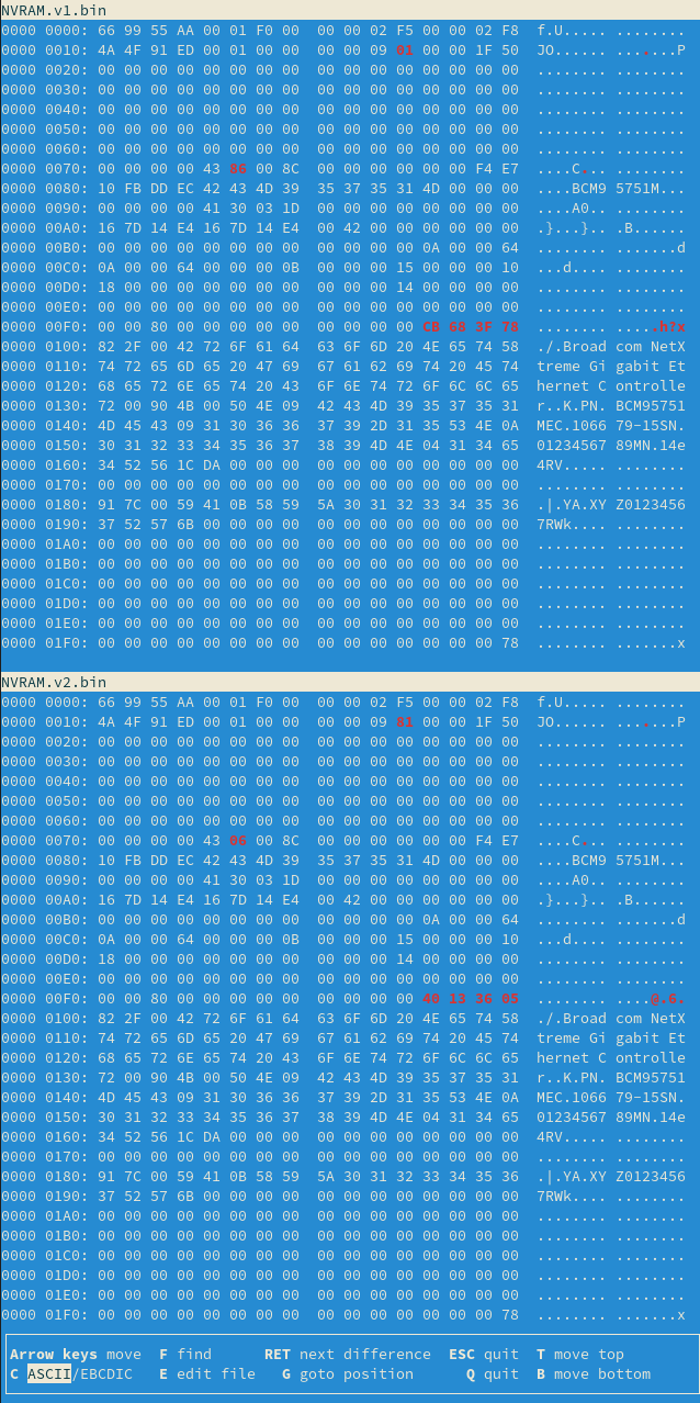
Overall, three changes stand out, within the first 512 bytes of NVRAM. Further below, we can see the whole OptionROM binary blob.
Running setpxe -d and then setpxe -e command generates the following binary differences:
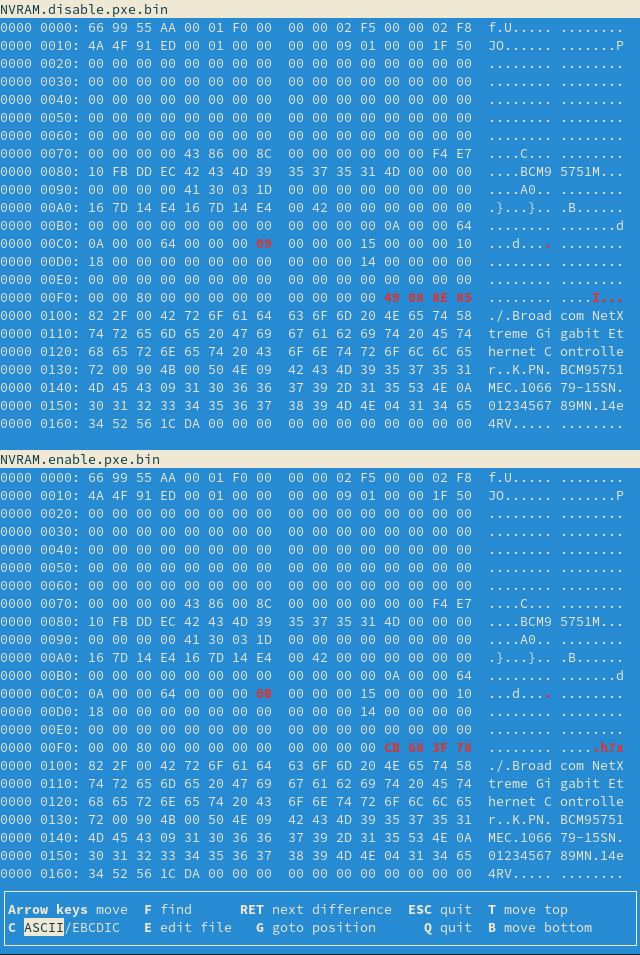
We see a single byte changing, probably a flag, and then 4 bytes that varied also with the first command.
Dispatching command line flags
A good starting point for reverse engineering the two commands is to look-up how command line flags
are dispatched. Occurrences of setpxe string such as the following:
0020767E aSetpxe_0 db 'setpxe',0 ; DATA XREF: dseg02:off_25B266o
and its offset (0020767E):
0025B266 offset_setpxe   dd offset aSetpxe_0     ; DATA XREF: cseg01:00031BC4
0025B266                                         ; cseg01:00031BD9 ...
0025B266                                         ; "setpxe"
lead us to a similar calls to sub_1531D such as the following:
00031C23 loc_31C23:                              ; CODE XREF: cseg01:00031C1A␘j
00031C23                 mov     edx, 65h
00031C28                 mov     eax, offset offset_setpxe
00031C2D                 call    sub_1531D
The only difference across several references to 0x25B266 are the hex values stored in edx.
In addition to 0x65, we also see 0x64 or 0x73, which are command line flags -e, -d, -s.
The parsing happens in multiple stages. We dereference first the content of [eax+8], i.e.
offset offset_setpxe + 8, checking that it is not 0:
0001531D sub_1531D       proc near               ; CODE XREF: cseg01:0001C717␙p
0001531D                                         ; sub_2F945+53␙p ...
0001531D                 push    4
00015322                 call    stack_overflow_outer_outer
00015327                 mov     eax, [eax+8]
0001532A                 test    eax, eax
0001532C                 jz      short loc_15346
We then start a loop where we compare edx with [eax] and in case they don’t match, we increase
eax by 0x14h and repeat.
Expand code - Command line arguments parsing
0001532E loc_1532E:                              ; CODE XREF: sub_1531D+27␙j
0001532E                 mov     dh, [eax]
00015330                 test    dh, dh
00015332                 jz      short loc_15346
00015334                 cmp     dl, dh
00015336                 jnz     short loc_15341
00015338                 mov     al, [eax+10h]
0001533B                 and     eax, 0FFh
00015340                 retn
00015341 ; ---------------------------------------------------------------------------
00015341
00015341 loc_15341:                              ; CODE XREF: sub_1531D+19␘j
00015341                 add     eax, 14h
00015344                 jmp     short loc_1532E
00015346 ; ---------------------------------------------------------------------------
00015346
00015346 loc_15346:                              ; CODE XREF: sub_1531D+F␘j
00015346                                         ; sub_1531D+15␘j
00015346                 xor     eax, eax
00015348                 retn
00015348 sub_1531D       endp
If we look through content of the data segment referenced in this code,
we’ll see that 0x64, 0x65, 0x73 are stored at 0x14 increments starting from [eax].
Expand code - Data segment with command line flags
0025B266 offset_setpxe   dd offset aSetpxe_0     ; DATA XREF: cseg01:00031BC4␘o
0025B266                                         ; cseg01:00031BD9␘o ...
0025B266                                         ; "setpxe"
0025B26A                 dd offset unk_206DAC
0025B26E                 dd offset unk_25B216
0025B272                 dd offset aEnableDisableP ; "Enable/Disable PXE"
0025B276                 dd offset aPxeSpeed0_Auto ; "PXE Speed:\n 0. auto  1. 10HD  2. 10FD  "...
0025B27A                 dd offset off_31AC7
0025B27E                 db    1
0025B27F                 db    0
0025B280                 db    0
0025B281                 db    0
0025B282                 db  10h
0025B283                 db    0
0025B284                 db    0
0025B285                 db    0
0025B286 unk_25B286      db  64h ; d             ; DATA XREF: dseg02:0025B2F2␙o
0025B287                 db    2
0025B288                 db    0
0025B289                 db    0
0025B28A                 dd offset aDisableMba   ; "Disable MBA"
0025B28E                 db    0
0025B28F                 db    0
0025B290                 db    0
0025B291                 db    0
0025B292                 db    0
0025B293                 db    0
0025B294                 db    0
0025B295                 db    0
0025B296                 db    0
0025B297                 db    0
0025B298                 db    0
0025B299                 db    0
0025B29A                 db  65h ; e
0025B29B                 db    5
0025B29C                 db    0
0025B29D                 db    0
0025B29E                 dd offset aEnableMbaProto ; "Enable MBA Protocol"
0025B2A2                 db    0
0025B2A3                 db    0
0025B2A4                 db    0
0025B2A5                 db    0
0025B2A6                 db    0
0025B2A7                 db    0
0025B2A8                 db    0
0025B2A9                 db    0
0025B2AA                 db    0
0025B2AB                 db    0
0025B2AC                 db    0
0025B2AD                 db    0
0025B2AE                 db  73h ; s
We are essentially trying to match the proper area of memory with the command line flag of interest,
returning [eax+10h], when we get a match. This latter address stores the value of the command
line flag. Based on the return value, the caller will decide how to dispatch further calls to
honor the input parameters.
Debug messages
Before moving ahead, it is worth having a look at how output is rendered by the tool. There are several debug messages distrubuted all over the code, and some do seem to be controlled by verbosity parameters. The more output the tool produces, the easier it will be to match its execution to code. In general, we see two types of output:
- Text I/O, implemented by writing to VGA video memory area at
0xA0000 - Graphical I/O implemented by writing into color text mode memory at
0xB8000
The corresponding pointers to the video memory areas are initialized in sub_1AC099:
001AC0EE                 mov     eax, [ebp+var_4]
001AC0F1                 mov     dword_2A0909, 400h
001AC0FB                 mov     dword_2A090D, (offset loc_AFFFF+1)
001AC105                 mov     dword_002A0911, 0B8000h
001AC10F                 mov     dword_002A0915, offset loc_A0000
001AC119                 mov     dword_2A0919, (offset loc_BFFFC+4)
An example of Text I/O could be the following:
0002A952                 push    offset aUpdatingDire_0 ; "Updating Directory...\n"
0002A957                 call    sub_0004182D
0002A95C                 add     esp, 4
0002A95F                 mov     edx, [esp+164h+var_30]
While an example of the Graphical I/O could be sub_16309, where the user sees a dialog and it’s expected
to continue or abort the operation:
00031C57                 jnz     short pxe_firmware_found_ram
00031C59                 push    offset aPxeFirmwareCan ; "PXE firmware cannot be found in NVRAM. "...
00031C5E                 call    sub_00016309
00031C63                 add     esp, 4
00031C66                 test    eax, eax
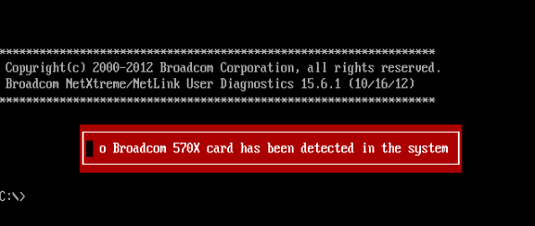
Following the I/O code is not straightforward, but dosbox emulator can help. The execution of the tool under dosbox
fails straight away becuse no adapter is found on the system, and the error messages is printed through Graphical I/O.
In the executions represented in the following screenshot, 32 bit program code seems to be pointed by segment selector 0868. One
can find empirically the offset between dosbox IP and linear address of the linear executable disassembled by IDA. This is useful to
be able to set breakpoints in the correct place. The code which implements Graphical I/O begins with loading address of a constant
pointing to color text mode memory:
00016122                 mov     eax, offset dword_258F24
00016127                 call    sub_16090
At 0x258F24 one can see the initialization value is set to 0x0B8000. eax can be considered a double pointer in this case. The actual write to
video memory happen happens at sub_15B88:
00015BA9 loc_15BA9:     ; CODE XREF: write_b8000_through_ec+Ej
00015BA9                 mov     ecx, [eax+4]
00015BAC                 test    ecx, ecx
00015BAE                 jz      short loc_15BBB
00015BB0                 mov     [ecx], dl
00015BB2                 mov     ecx, [eax+4]
00015BB5                 mov     dl, [eax+1Ch]
00015BB8                 mov     [ecx+1], dl
The state of the execution is very clear from the dosbox screenshot below. ECX holds the pointer to video memory, while
EDX holds the value to be written and mov [ecx], dl implements the actual write.
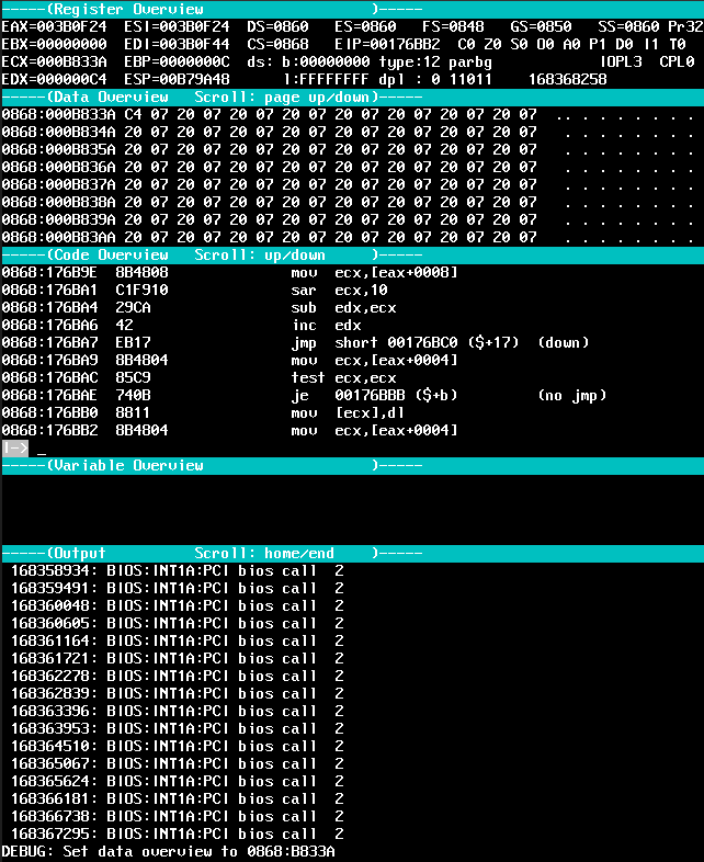
We can double check that at B833A or any address close by are actually backing video memory.
dosbox command sm 0868:<OFFSET> 0x0 will write a null 16 bits at that address. That becomes clearly visible from the output
Similarly, text mode output is implemented by writing to VGA memory area, at 0xA0000:
001ACDFC loc_1ACDFC:                             ; CODE XREF: write_to_monochrome_address+20j
001ACDFC                 mov     eax, dword_002A0915
001ACE01                 mov     di, word_2A0903
[...]
001ACE4B                 add     edx, esi
001ACE4D                 mov     es:[eax], dx
While following these control paths, I noticed that at the beginning of sub_0004182D, which we have seen it referenced
above with the “Updating directory” message, there is a check on a flag that might result in the function beeing a no-op:
0004183E                 test    byte ptr <FLAG_ADDR>, 1
00041845                 jz      <END>
0004184B                 lea     eax, [esp+1Ch]
0004184F                 mov     [esp], eax
00041852                 mov     ebx, es
<FLAG_ADDR> is accessed in multiple places in write mode, but it seemed to be set to 1 in all my executions, resulting
in not having any of the debug messages that I could see referenced in code. I could not find a way to flip the value of <FLAG_ADDR> through
the tool, so I just resorted to chaing jz into jnz and I got a whole lot more of debug messages that helped me map the execution to code.
Writing NVRAM
The main function responsible for altering the content of NVRAM is sub_8708A, where we can see a known refernce
to eecfg_write verbose log output:
000870B3 push offset aEecfg_writeOff ; "\neecfg_write, offset=0x%x, len=0x%x; "
Foundamentally, sub_8708A ends up writing to NVM write/read interface registers, as outlined by the specs referenced
at the beginning of the post. In particular, we can see the code writing to Command Register (with wr bit set),
Address Register and Write Register:
Expand code - Acccess to Command, Address and Write registers
00022A9B loc_22A9B:                              ; CODE XREF: write_through_7008_2+F␘j
00022A9B                 mov     eax, 7008h
00022AA0                 call    write_to_register
00022AA5                 test    bl, 80h
00022AA8                 jz      short loc_22AB6
00022AAA                 mov     edx, esi
00022AAC                 mov     eax, 700Ch
00022AB1                 call    write_to_register
00022AB6
00022AB6 loc_22AB6:                              ; CODE XREF: write_through_7008_2+23␘j
00022AB6                 or      bl, 38h
00022AB9                 mov     edx, ebx
00022ABB                 mov     eax, 7000h
00022AC0                 call    write_to_register
00022AC5                 call    sub_221B0
00022ACA                 test    eax, eax
00022ACC                 jz      short loc_22AD2
00022ACE                 xor     eax, eax
00022AD0                 pop     esi
00022AD1                 retn
Enabling PXE with pxe -e
pxe command is relatively straightforward. After interpreting command line flags, we dispatch a programming request
to sub_A1CA8. On the pxe -e control path, we can see the following invocation:
00031C36                 push    0
00031C38                 mov     ecx, 2
00031C3D                 mov     ebx, ecx
00031C3F                 mov     edx, esi
00031C41                 xor     eax, eax
00031C43                 call    sub_A1CA8
while on the pxe -d control path, we have the following:
00031CAB                 push    1
00031CAD                 xor     ecx, ecx
00031CAF                 mov     ebx, 2
00031CB4
00031CB4 loc_31CB4:                              ; CODE XREF: cseg01:00031DCD␙j
00031CB4                 mov     edx, esi
00031CB6                 xor     eax, eax
00031CB8                 call    sub_A1CA8
The two main differences that stand out are the first stack argument, 0 or 1 and the value in ecx, 2 and 0.
If we follow sub_A1CA8, we land on sub_A1C0F, which performs the actual enablement and disablement:
000A1C7F loc_A1C7F:                              ; CODE XREF: enabling_disabling+69␘j
000A1C7F                 test    edx, ecx
000A1C81                 jz      short loc_A1C8F
000A1C83                 mov     ebx, edx
000A1C85                 not     ebx
000A1C87                 and     ebx, [esi]
000A1C89                 and     edx, ecx
000A1C8B                 or      edx, ebx
000A1C8D                 jmp     short loc_A1C93
000A1C8F ; ---------------------------------------------------------------------------
000A1C8F
000A1C8F loc_A1C8F:                              ; CODE XREF: enabling_disabling+72␘j
000A1C8F                 not     edx
000A1C91                 and     edx, [esi]
test edx, ecx dispatches execution to either enablment, if values differ, or disablement, if values are equal, of PXE.
Within sub_A1CA8, a sample call to sub_A1C0F is the following:
000A2091                 push    offset pxe_offset
000A2096                 push    2
000A2098                 mov     ecx, [esp+34h]
000A209C                 mov     ebx, [esp+30h]
000A20A0                 mov     edx, esi
000A20A2                 lea     eax, [esp+10h]
We can make the following observations:
- The numeric argument on the stack, 2 in this case, is the initialization value of
edxin thetestinstruction - The value of
ecx, i.e.[esp+34h], is retained bysub_A1C0Fand it’s directly used in thetestinstruction
If we look up how the stack is managed by sub_A1CA8, we can see the following:
-
sub esp, 30hat000A1CB5 -
mov [esp+2Ch], ecxat000A1CC0 - Before invoking
sub_A1C0Fwe always have two additionalpush, which consititue the only source of change foresp. Therefore, we can conclude that-30h+2Chis equal to-30h-8h (double push)+34, i.e.-4and the value used bysub_A1C0Fin thetestinstructions is theecxfromsub_A1CA8’s caller. As we have seen earlier, flag-esetsecxto 2, while flag-dsetsecxto 0.
Eventually, PXE enablment is done by set a single bit, at exactly the position indicated by edx.
000A1C7F loc_A1C7F:                              ; CODE XREF: enabling_disabling+69␘j
000A1C7F                 test    edx, ecx
000A1C81                 jz      short loc_A1C8F
000A1C83                 mov     ebx, edx
000A1C85                 not     ebx
000A1C87                 and     ebx, [esi]
000A1C89                 and     edx, ecx
000A1C8B                 or      edx, ebx
000A1C8D                 jmp     short loc_A1C93
Conversely, disablement is done by resetting that same bit, by inverting position bit in edx:
000A1C8F loc_A1C8F:                              ; CODE XREF: enabling_disabling+72␘j
000A1C8F                 not     edx
000A1C91                 and     edx, [esi]
The pre-existing word that is having one bit flipped is copied back to [esi] which is set to the address of buffer in memory that will be
written to NVRAM. Later in the function We can sett references to NVRAM write routine eecfg_write, with the corresponding offset
0xC4 that stands out from the NVRAM dump seen earlier.
Expand code - Write PXE enablement flag at 0xC4 offset
000A2561 loc_A2561:                              ; CODE XREF: program_nvram+85A␘j
000A2561                 mov     edx, [esp]
000A2564                 and     edx, 0FF000000h
000A256A                 shr     edx, 18h
000A256D                 mov     eax, [esp]
000A2570                 and     eax, 0FF0000h
000A2575                 shr     eax, 8
000A2578                 or      edx, eax
000A257A                 mov     eax, [esp]
000A257D                 and     eax, 0FF00h
000A2582                 shl     eax, 8
000A2585                 or      edx, eax
000A2587                 mov     eax, [esp]
000A258A                 and     eax, 0FFh
000A258F                 shl     eax, 18h
000A2592                 or      edx, eax
000A2594                 mov     [edi+0C4h], edx
000A259A                 lea     edx, [edi+0C4h]
000A25A0                 mov     ecx, 4
000A25A5                 mov     ebx, 0C4h
000A25AA                 xor     eax, eax
000A25AC                 call    eecfg_write
000A25B1                 test    eax, eax
000A25B3                 jnz     loc_A243D
000A25B9                 push    offset aVerifyingNvram ; "\nVerifying NVRAM checksum"
There are actually multiple references to eecfg_write, and these seem to be executed based on the NIC model. This means that different
NICs might store PXE enablement flag at different offsets. The PXE enablement NVRAM dump also highlights a 4 bytes change at 0xFC. As we’ll
see for setpxe command, this is checksum value calculated over low addresses of NVRAM.
Writing OptionROM with setpxe
The low address range of the NVRAM stores a table of metadata which is referred to as
“directory”. This metadata indicates where various NVRAM blobs are located, including
PXE payload. sub_2BB4D goes through this table to find an entry which refers to PXE
binary, with each entry identified with an id and the base directory holding
8 entries at most. There exists also the concept of extended directory, which is not covered
in this exercise. The code iterates through entries [0,8[ and under certain conditions, it
copies their content to memory. ecx is used store the index of the current entry
in NVRAM and edi stores directory base address in memory:
0002BBA9 loc_2BBA9:                              ; CODE XREF: dir_find_entry+50j
0002BBA9                 mov     eax, ecx
0002BBAB                 shl     eax, 2
0002BBAE                 sub     eax, ecx
0002BBB0                 shl     eax, 2
0002BBB3                 add     eax, edi
This code already reveals important information on how the directory is structured. Starting
from an index, as per the code above NVRAM is addressed as (((4*index-index)*4)+<BASE>)+<OFFSET>, i.e.
12*index+<BASE>+<OFFSET>, suggesting that every item in the table is 12 bytes long.
We first fetch 4 bytes content at +4 offset and reverse its endianess, using esp+1Ch+var_14 as temporary storage.
Expand code - First byte of entry in directory
0002BBB5                 mov     edx, [eax+4]
0002BBB8                 and     edx, 0FF000000h
0002BBBE                 shr     edx, 18h
0002BBC1                 mov     [esp+1Ch+var_14], edx
0002BBC5                 mov     edx, [eax+4]
0002BBC8                 and     edx, 0FF0000h
0002BBCE                 shr     edx, 8
0002BBD1                 mov     ebx, [esp+1Ch+var_14]
0002BBD5                 or      ebx, edx
0002BBD7                 mov     edx, [eax+4]
0002BBDA                 and     edx, 0FF00h
0002BBE0                 shl     edx, 8
0002BBE3                 or      ebx, edx
0002BBE5                 mov     edx, [eax+4]
0002BBE8                 and     edx, 0FFh
0002BBEE                 shl     edx, 18h
0002BBF1                 or      edx, ebx
We then skip the entry in the following cases:
- The content at offset +4 is
0x3FFFFF - Bits
[24,31]of the word at offset +4 are != 0x10
0002BBF3                 test    edx, offset unk_3FFFFF
0002BBF9                 jz      short loc_2BB9F
0002BBFB                 shr     edx, 18h
0002BBFE                 and     edx, 0FFh
0002BC04                 cmp     edx, 10h
0002BC07                 jnz     short loc_2BB9F
Bits [24,31] have a have a special meaning, which we’ll see later. If the entry is not skipped,
we copy the content at +8 into ebp and call sub_B19EA:
0002BC3E                 lea     edx, [edi+60h]
0002BC41                 mov     ebx, 30h
0002BC46                 mov     eax, ebp
0002BC48                 call    sub_B19EA
Through sub_B19EA, we ask to fetch NVRAM data from offset in ebp, which we just read at <DIRECTORY_ENTRY>+8
for a length of 0x30*4 into destination address in edx. We derive the meaning of these parameters by
following sub_B19EA and seeing that it increments the source and destination addresses by 4 until we
reach the desired length:
000B19F7                 mov     esi, eax
000B19F9                 mov     ecx, edx
000B19FB                 mov     edi, ebx
[...]
000B19FD                 xor     ebx, ebx
000B19FF
000B19FF loc_B19FF:                              ; CODE XREF: copy_nvram_data?+6Aj
000B19FF                 cmp     ebx, edi
[...]
000B1A03                 mov     edx, ecx
000B1A05                 add     ecx, 4
[...]
000B1A50                 inc     ebx
000B1A51                 add     esi, 4
Further down the stack, we have a write to [ebx], which is originally edi+0x60:
000B0E16                 mov     eax, 6838h
000B0E1B                 call    sub_21263
000B0E20                 mov     [ebx], eax
Register 0x6838 seems to be undocumented, and I can only speculate it implementes NVRAM read interface.
We saw earlier that there are 8 entries in the directory each one 12 bytes long, overall 0x60 bytes, and edi
still holds the base address of the NVRAM in destination memory. If we succeed in finding an entry that triggers
the copy, we set a flag in [esp+1Ch+var_18]:
0002BC55 mov [esp+1Ch+var_18], 1
and then decide where to dispatch execution:
0002BC62 loc_2BC62:                              ; CODE XREF: dir_find_entry+56j
0002BC62                 cmp     [esp+1Ch+var_10], 80h
0002BC67                 jb      loc_2BDA4
0002BC6D                 cmp     [esp+1Ch+var_18], 0
0002BC72                 jz      loc_2BD96
0002BC78                 xor     ecx, ecx
0002BC7A                 jmp     short loc_2BC86
esp+1Ch+var_10 is 0x0 and represent the id of the entry we are trying to add to the table.
As this is < 0x80, we jump further ahead. If instead the id was > 0x80 and esp+1Ch+var_18
was 0x0 we would jump to a control path where what stands out is:
0002A277                 push    edx
0002A278                 push    offset aDircreate_extd ; "\ndirCreate_Extdir.
This seems to be creating the extended directory table, so we can speculate that the leftmost
byte of the field in the directory entry, which earlier we checked against 0x10, might indicate its type,
and 0x10 might represent the extended directory. When attempting to add an entry with
id > 0x80, which at this point is unclear what it represents, if the extended directory is not
found, it gets created.
esi contains the callers’ esp+140h+var_1C, where it expects to find an entry id to use. Once
past the look-up of the extended directory, we start scanning through the base entries in the
directory table, starting from 0:
0002BDA4 loc_2BDA4:                              ; CODE XREF: dir_find_entry+11Aj
0002BDA4                 mov     dword ptr [esi], 0
0002BDAA                 jmp     short loc_2BDBA
We then follow a similar pattern seen before, and check content at +4 offset against
0x3FFFFF.
Also similarly to the first scan, we check bits [24,31] against esp+1Ch+var_10, which we now know for sure
contains the id of the entry (0x0 for PXE).
0002BE06                 mov     ecx, edx
0002BE08                 shr     ecx, 18h
0002BE0B                 and     ecx, 0FFh
0002BE11                 xor     edx, edx
0002BE13                 mov     dl, [esp+1Ch+var_10]
0002BE17                 cmp     ecx, edx
If we find an entry with a matching id, we perform an additional check:
0002BE1B                 cmp     [esp+1Ch+var_1C], 0
0002BE1F                 jz      loc_2BD21
0002BE25                 mov     dword ptr [eax+4], 0
esp+1Ch+var_1C is a flag passed by the caller, with value 0x1. We then
zero out the value at offset +4 and exit, with the entry id in [esi] for
the caller to find. After having identified an entry in the table,
we look for NVRAM space to host the data and we’ll see in the next section exactly
which strategy is used by the code to locate this space.
0002AFF1                 mov     ebx, [esp+140h+var_14]
0002AFF8                 lea     edx, [esp+140h+var_20]
0002AFFF                 mov     eax, esp
0002B001                 call    sub_29682
We then set new values in the directory entry. We see a similar pattern as before: if the ID is > 0x80,
we jump to the extended directory update section, otherwise we follow the base directory update path.
0002B0F3 loc_2B0F3:                              ; CODE XREF: program_NVRAM_maybe_update_directory+1CDj
0002B0F3                                         ; program_NVRAM_maybe_update_directory+1E1j
0002B0F3                 mov     eax, [esp+140h+var_1C]
0002B0FA                 push    eax
0002B0FB                 push    offset aDirwriteIndexI ; "\ndirWrite, index is %x."
0002B100                 call    verbosity_8
0002B105                 add     esp, 8
0002B108                 mov     edx, [esp+140h+var_1C]
0002B10F                 cmp     edx, 80h
0002B115                 jl      loc_2B3E6
Before moving forward, we must note that the lenght of the OptionROM, stored in esp+140h+var_14
is aligned to 4 bytes boundaries and increased by 4, as the OptionROM data region will contain
also a trailing checksum:
0002AFB0                 test    byte ptr [esp+140h+var_14], 3
0002AFB8                 jz      short loc_2AFCD
0002AFBA                 mov     eax, [esp+140h+var_14]
0002AFC1                 and     al, 0FCh
0002AFC3                 add     eax, 4
0002AFC6                 mov     [esp+140h+var_14], eax
Furthermore esp+140h+var_14 does not store the raw length alone. The value is multiplied by 4
as it represents the number of double words (4 bytes). esp+140h+var_10, which is the id
of the entry, is then stored in the 8 most significant bits of the same word:
0002B0A5                 mov     ecx, [esp+140h+var_14]
0002B0AC                 shr     ecx, 2
0002B0AF                 mov     [esp+140h+var_14], ecx
0002B0B6                 xor     eax, eax
0002B0B8                 mov     al, [esp+140h+var_10]
0002B0BF                 shl     eax, 18h
0002B0C2                 mov     ebx, ecx
0002B0C4                 or      ebx, eax
The resulting value is written to at +4 of the selected index in the directory.
Expand code - Write at +4 offset of the item in directory
0002B3E6 loc_2B3E6:                              ; CODE XREF: program_NVRAM_maybe_update_directory+20Dj
0002B3E6                 mov     ecx, [esp+140h+var_14]
0002B3ED                 and     ecx, 0FF000000h
0002B3F3                 shr     ecx, 18h
0002B3F6                 mov     eax, [esp+140h+var_14]
0002B3FD                 and     eax, 0FF0000h
0002B402                 shr     eax, 8
0002B405                 or      ecx, eax
0002B407                 mov     eax, [esp+140h+var_14]
0002B40E                 and     eax, 0FF00h
0002B413                 shl     eax, 8
0002B416                 or      ecx, eax
0002B418                 mov     eax, [esp+140h+var_14]
0002B41F                 and     eax, 0FFh
0002B424                 shl     eax, 18h
0002B427                 or      ecx, eax
0002B429                 mov     eax, edx
0002B42B                 shl     eax, 2
0002B42E                 sub     eax, edx
0002B430                 mov     [esp+eax*4+4], ecx
At offset +0, a value set by the caller gets written. On the PXE update path, it seems to be
always 0x100000, which is coherent with the dumps of the NVRAM seen earlier.
Expand code - Write at +0 offset of the item in directory
0002B434                 mov     ecx, esi
0002B436                 and     ecx, 0FF000000h
0002B43C                 shr     ecx, 18h
0002B43F                 mov     edx, esi
0002B441                 and     edx, 0FF0000h
0002B447                 shr     edx, 8
0002B44A                 or      ecx, edx
0002B44C                 mov     edx, esi
0002B44E                 and     edx, 0FF00h
0002B454                 shl     edx, 8
0002B457                 or      edx, ecx
0002B459                 mov     ecx, esi
0002B45B                 and     ecx, 0FFh
0002B461                 shl     ecx, 18h
0002B464                 or      edx, ecx
0002B466                 mov     [esp+eax*4], edx
At offset +8 we write the NVRAM address returned by sub_29682, the function which looks up space in NVRAM.
Expand code - Write at +8 offset of the item in directory
0002B469                 mov     ecx, [esp+140h+var_20]
0002B470                 and     ecx, 0FF000000h
0002B476                 shr     ecx, 18h
0002B479                 mov     edx, [esp+140h+var_20]
0002B480                 and     edx, 0FF0000h
0002B486                 shr     edx, 8
0002B489                 or      ecx, edx
0002B48B                 mov     edx, [esp+140h+var_20]
0002B492                 and     edx, 0FF00h
0002B498                 shl     edx, 8
0002B49B                 or      edx, ecx
0002B49D                 mov     ecx, [esp+140h+var_20]
0002B4A4                 and     ecx, 0FFh
0002B4AA                 shl     ecx, 18h
0002B4AD                 or      edx, ecx
0002B4AF                 mov     [esp+eax*4+8], edx
NVRAM is then overwritten with the dirty directory stored in memory. Overall, we can summarize the meaning of each of the 3 fields on a directory entry as follows:
- Offset
+0stores a constant of value0x100000, at least for PXE entry types - Offset
+4stores a word containing the lenght of the entry in the 24 least significant bits and the entry id in the 8 most significant bits - Offset
+8stores the offset of the entry in NVRAM
NVRAM space look-up
sub_29682 implements the algorithm to find space in NVRAM for the new binary. The code simply iterates through all directory
entries and tries to identify a start address which doesn’t overlap with any existing blob. At every iteration through the directory,
the candidate address for the new OptionROM could be located in 4 different configurations with respect at the current entry in the directory, as follows:
The candidate address + the OptionROM size could be located at lower addresses with respect to the current entry, with no overlap.
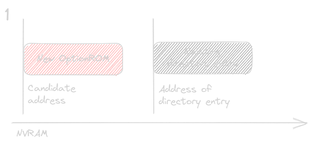
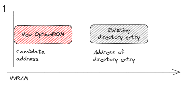
The candidate address + the OptionROM size could be located at lower addresses with respect to the current entry, with partial or full overlap.
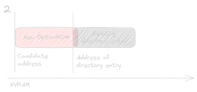
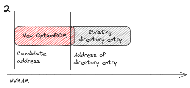
The candidate address is located past the address of the existing directory item + the size of the item.
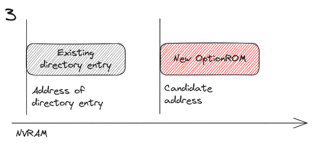
The candidate address is located past the address of the existing directory item start address, but it overlaps partially or entirely with it.
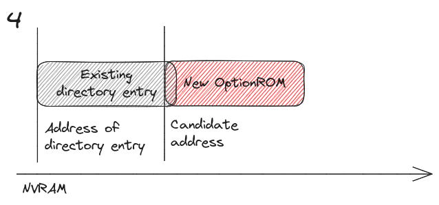
In case 1 and 3, the algorithm moves to the next directory item. In case 2 and 4, candidate address of the OptionROM is re-initialized to the end of the existing directory item, calculated as its start address + size. Then, the iteration through the directory items starts all over from the beginning.
We can see the candidate address of the new OptionROM is always pushed to higher addresses.
It’s interesting to look closer into how the address and size of the initial existing directory entry are
selected, together with the default candidate address of the OptionROM, as it provides relevant insights
over the layout of the NVRAM. The following investigation suggests that before the directory, there exists
a set of metadata indicating the offset and size of what could be NIC firmware code, which obviously cannot
be overwritten by OptionROM code, and therefore is used to initialize the default existing directory entry values.
The initialization is performed at 0x2973A, where sub_29543 is invoked to extract additional NVRAM information as follows:
- We read 8 bytes from offset
0x8throughsub_B119EA. This funcion is analyzed in the next section, for now we can assume it copies data from NVRAM into memory. NVRAM starts with the0xAA559966signature which is immediately followed by a first set of metadata just before the beginning of NVRAM directory. We split these 8 bytes in two words, the former of which we’ll see in a moment represents a size, while the latter represents an offset. - At
0x295A1, we callsub_25C1D, which performs a check on the type of the EEPROM that controls whether additional NVRAM page checking code needs to be executed. I haven’t fully reversed the EEPROM type check, but we can easily derive that the function invoked at0x295ACreturns the actual page size based on the page size selector stored in register0x7014. My assumption is therefore that EEPROM type check verifies if we are working with paged storage.
Expand - Page checking code
000248D8 loc_248D8:                              ; CODE XREF: sub_2488F+11␘j
000248D8                                         ; sub_2488F+1A␘j ...
000248D8                 mov     eax, 7014h
000248DD                 call    read_reagister_pci_space
000248E2                 and     eax, 70000000h
000248E7                 jnz     short loc_248EF
000248E9                 mov     eax, 100h
000248EE                 retn
000248EF ; ---------------------------------------------------------------------------
000248EF
000248EF loc_248EF:                              ; CODE XREF: sub_2488F+58␘j
000248EF                 cmp     eax, 10000000h
000248F4                 jnz     short loc_248FC
000248F6                 mov     eax, 200h
000248FB                 retn
000248FC ; ---------------------------------------------------------------------------
000248FC
000248FC loc_248FC:                              ; CODE XREF: sub_2488F+65␘j
000248FC                 cmp     eax, 20000000h
00024901                 jnz     short loc_24909
00024903                 mov     eax, 400h
00024908                 retn
00024909 ; ---------------------------------------------------------------------------
00024909
00024909 loc_24909:                              ; CODE XREF: sub_2488F+72␘j
00024909                 cmp     eax, 30000000h
0002490E                 jnz     short loc_24916
00024910                 mov     eax, 800h
00024915                 retn
00024916 ; ---------------------------------------------------------------------------
00024916
00024916 loc_24916:                              ; CODE XREF: sub_2488F+7F␘j
00024916                 cmp     eax, 40000000h
0002491B                 jnz     short loc_24923
0002491D                 mov     eax, 1000h
00024922                 retn
00024923 ; ---------------------------------------------------------------------------
00024923
00024923 loc_24923:                              ; CODE XREF: sub_2488F+8C␘j
00024923                 cmp     eax, 50000000h
00024928
00024928 loc_24928:                              ; CODE XREF: sub_2488F+47␘j
00024928                 mov     eax, 108h
0002492D                 retn
Among all the possible page sizes, the code seems to perform ad-hoc operations only with 264 bytes pages.
In particular, we take the second word we just read at +8+4 and translate it from from
512 to 264 bytes pages with (<OFFSET>/512)*264+<OFFSET>%512:
0002497A                 call    sub_2488F
0002497F                 cmp     eax, 108h
00024984                 jnz     short loc_249A0
00024986                 mov     ecx, edx
00024988                 shr     ecx, 9
0002498B                 mov     eax, ecx
0002498D                 shl     eax, 5
00024990                 add     eax, ecx
00024992                 shl     eax, 3
00024995                 and     edx, 1FFh
0002499B                 add     eax, edx
0002499D                 pop     edx
0002499E                 pop     ecx
0002499F                 retn
000249A0 ; ---------------------------------------------------------------------------
000249A0
000249A0 loc_249A0:                              ; CODE XREF: sub_2496C+18␘j
000249A0                 mov     eax, edx
000249A2                 pop     edx
000249A3                 pop     ecx
000249A4                 retn
000249A4 sub_2496C       endp
It’s not clear to me why only 264 bytes pages are rescaled. My NIC is fitted with an AT45DB011 flash memory, which uses exactly 264
bytes pages, so this conversion will be relevant later. The rescaled value eventually gets stored in [esi]. We then
mutiply the first word by 4, suggesting, or confirming, that it represents a size. From rescaled offset and size, we fetch more NVRAM content.
Expand - Fetching NVRAM content at offset+size
000295B3 loc_295B3:                              ; CODE XREF: copy_stage1_regions_nvram?+65␘j
000295B3                 mov     edx, [esp]
000295B6                 and     edx, 0FF000000h
000295BC                 shr     edx, 18h
000295BF                 mov     eax, [esp]
000295C2                 and     eax, 0FF0000h
000295C7                 shr     eax, 8
000295CA                 or      eax, edx
000295CC                 mov     edx, [esp]
000295CF                 and     edx, 0FF00h
000295D5                 shl     edx, 8
000295D8                 or      edx, eax
000295DA                 mov     eax, [esp]
000295DD                 and     eax, 0FFh
000295E2                 shl     eax, 18h
000295E5                 or      eax, edx
000295E7                 shl     eax, 2
000295EA                 mov     [ecx], eax
000295EC                 mov     eax, [esi]
000295EE                 add     eax, [ecx]
000295F0                 mov     ebx, 2
000295F5                 mov     edx, esp
000295F7                 call    copy_nvram_data?
We can try to replicate the operations above on a real NVRAM binary dump, using the following data:
- Size
$ xxd -l 4 -seek 8 -C NVRAM.v2.bin 00000008: 0000 02f5 - Offset
xxd -l 4 -seek 12  -C NVRAM.v2.bin
0000000c: 0000 02f8
The offset, 0x2F8, needs to be rescaled as our NVRAM uses 264 bytes pages. Size,0x2F5, is instead multiplied by +4. The final address for additional content becomes therefore (0x2F8/512)*264+0x2F8%512+0x2F5*4,
i.e. 1*264+248+757*4=0xDD4. From the resulting address, if we encounter 0xAA559966, which is the header magic numer,
we fetch the word at offset +4, which seems to represent another size, add 8 and sum it up with the offset that got us to this new header.
In this example, we do see header magic at 0xDD4:
$ xxd -l 4 -seek 0xDD4  -C NVRAM.v2.bin
00000dd4: 6699 55aa
and the next word is 0x1174:
$ xxd -l 4 -seek 0xDD8  -C NVRAM.v2.bin
00000dd8: 0000 1174
Combining all this together, we get 0xDD4+8+0x1174=0x1F50, which we can see it corresponds to the
offset of the existing OptionROM in the NVRAM, stored in the 4 bytes at 0x1C in the corresponding
directory entry:
$ xxd -l 4 -seek 0x1C  -C NVRAM.v2.bin
0000001c: 0000 1f50
Expand - Final offset calculation
0002962F                 cmp     eax, 669955AAh
00029634                 jnz     short loc_29679
00029636                 mov     edx, [esp+4]
0002963A                 and     edx, 0FF000000h
00029640                 shr     edx, 18h
00029643                 mov     eax, [esp+4]
00029647                 and     eax, 0FF0000h
0002964C                 shr     eax, 8
0002964F                 or      edx, eax
00029651                 mov     eax, [esp+4]
00029655                 and     eax, 0FF00h
0002965A                 shl     eax, 8
0002965D                 or      edx, eax
0002965F                 mov     eax, [esp+4]
00029663                 and     eax, 0FFh
00029668                 shl     eax, 18h
0002966B                 or      eax, edx
0002966D                 add     eax, 8
00029670                 add     [ecx], eax
00029672                 mov     eax, 1
00029677                 jmp     short loc_2967B
Essentially, the math adds up.
Integrity checksums
There are multiple integrity values stored in NVRAM. Two are immediately obvious from the binary diff
shown at the beginning of the post, i.e. a 1 byte checksum at offset 0x75 and a 4 bytes checksum at
offset 0xFC, in the directory area. There is also a third “hidden” checksum covering the OptionROM
binary itself. In fact, we have seen earlier that the OptionROM size stored in the directory corresponds
to the size of the binary +4 bytes, indicating that something is appended to the EFI blob.
sub_2AF08 is the main function which programs NVRAM data and directory metadata and sub_2BEAD gets
us to the calculation of the integrity values:
0002BF0E                 mov     ebx, 1
0002BF13                 mov     edx, 60h
0002BF18                 lea     eax, [esp+8Ch]
0002BF1F                 call    sub_4F781
0002BF24                 mov     [esp+1], al
0002BF28                 mov     ebx, 0FFFFFFFFh
0002BF2D                 mov     edx, 88h
0002BF32                 mov     eax, esp
0002BF34                 call    sub_67BF9
0002BF39                 mov     [esp+88h], eax
0002BF40                 mov     edx, eax
0002BF42                 not     edx
0002BF44                 mov     [esp+88h], edx
0002BF4B                 mov     ebx, 23h
0002BF50                 mov     edx, esp
0002BF52                 mov     eax, 74h
[esp+1] and [esp+88h] indicate the destination address of the resulting value of sub_4F781 and sub_67BF9,
which we’ll see are checksum calculation routines. The+1 and +88h offsets of the memory buffer can be mapped to
the binary diff of the NVRAM area, where we have a 1 byte difference at 0x75 and 4 bytes difference
at 0xFC. The two pairs of offsets are equally distancesd, so if esp+88h = 0xFC, then esp == 0x74 and esp+1 == 0x75.
sub_4F781 and sub_4F781 calculate integrity values respectively on 0x60 and 0x88 bytes read from
NVRAM through sub_B119EA. We see two invocations of sub_B119EA, which prepare the data to be checksummed:
0002BEC0                 mov     ebx, 18h
0002BEC5                 lea     edx, [esp+8Ch]
0002BECC                 mov     eax, 14h
0002BED1                 call    sub_B119EA
and
0002BEF9                 mov     ebx, 23h
0002BEFE                 mov     edx, esp
0002BF00                 mov     eax, 74h
0002BF05                 call    sub_B119EA
The meaning of the parameters are the following:
-
eaxcontains the offset in NVRAM from which to copy the data over to[esp+8C]and[esp] -
ebxcontains the size to be copied still to be intended as the number of double words (4 bytes. This can be easily seen by followingsub_B119EA)
Once the data is available sub_4F781 and sub_67BF9 calculate respectively 1 and 4 bytes checksums. Here Ghidra provides relatively
accurate decompiled versions of the two functions.
sub_4F781: 1 byte checksum, Ghidra decompiled code
uint __regparm3 UndefinedFunction_0004f78b(char *param_1,int param_2)

{
  char unaff_BL;
  byte bVar1;

  bVar1 = 0;
  while (param_2 = param_2 + -1, param_2 != -1) {
    bVar1 = bVar1 + *param_1;
    param_1 = param_1 + 1;
  }
  if (unaff_BL != '\0') {
    return (uint)param_1 & 0xffffff00 | (uint)(byte)(~bVar1 + 1);
  }
  return (uint)param_1 & 0xffffff00 | (uint)bVar1;
}
sub_67BF9: 4 bytes checksum, Ghidra decompiled code
uint __regparm3 UndefinedFunction_00067c06(byte *param_1,uint param_2)

{
  uint uVar1;
  uint uVar2;
  uint unaff_EBX;
  uint uVar3;
  uint uVar4;

  for (uVar4 = 0; uVar4 < param_2; uVar4 = uVar4 + 1) {
    uVar2 = (uint)*param_1;
    uVar1 = 0;
    param_1 = param_1 + 1;
    do {
      if (((unaff_EBX ^ uVar2) & 1) == 0) {
        uVar3 = 0;
      }
      else {
        uVar3 = 0xedb88320;
      }
      unaff_EBX = unaff_EBX >> 1 ^ uVar3;
      uVar2 = uVar2 >> 1;
      uVar1 = uVar1 + 1;
    } while (uVar1 < 8);
  }
  return unaff_EBX;
}
We can then summarize these first two integrity values as follows:
- We copy
96(0x60) bytes from NVRAM starting at offset0x14, and calculate a 1 byte checksum. We copy this checksum to offset0x75. This region of memory is the directory, 8 entries of 12 bytes each. - We copy
140(0x88) bytes from NVRAM starting at offset0x74, and calculate a 4 byte checksum. We copy this checksum to offset0xFC. This region of memory seems to be containing other VPD data.
We get to a similar conclusion for the integrity check of the OptionROM itself. In the main PXE update function, sub_98542, we can first track the size of the image:
000986E8 loc_986E8:                              ; CODE XREF: sub_98542+17E
000986E8                 push    edi
000986E9                 push    offset aLengthDBytes__ ; "(length = %d bytes ) ...\n"
If we follow edi backwards, we can track the invocation of sub_67BF9, the routine which calculates the 4 bytes checksum:
00098678                 mov     edx, edi
0009867A                 mov     eax, esi
0009867C                 call    sub_67BF9
00098681                 mov     edx, eax
00098683                 not     edx
00098685                 lea     eax, [esi+edi]
00098688                 mov     [eax], edx
0009868A                 push    offset aUpdatingPxe ; "Updating PXE "
0009868F                 xor     eax, eax
00098691                 mov     al, [esp+44h+var_10]
00098695                 push    eax
00098696                 add     edi, 4
The only argument to sub_67BF9 is the size of the image, which doesn’t include yet the 4 additional bytes.
The result is stored at esi+edi, i.e. the base address of the OptionROM in memory + its length. The lenght of the image
is then increased by 4 before being stored in the directory.
Updating VendorID and DeviceID
A final operation that B57UDIAG.EXE tool performs is updating VendorID and DeviceID in the OptionROM header, according to the device where the
OptionROM is being written to. In my experiments using Tianocore EDKII, I have always generated the OptionROM directly with the correct IDs, through
EfiRom:
./BaseTools/Source/C/bin/EfiRom -f 0x167d -i 0x14e4 -e Build/OvmfX64/DEBUG_GCC5/X64/OptionROM/OptionROM/DEBUG/OptionROM.efi -o OptionROM.final.efi
Overwriting Vendor and Device IDs at flash time is clearly much more flexible. The tool I have written based on this exercise does not currently perform this operation and fully relies on the header generated at build time.